


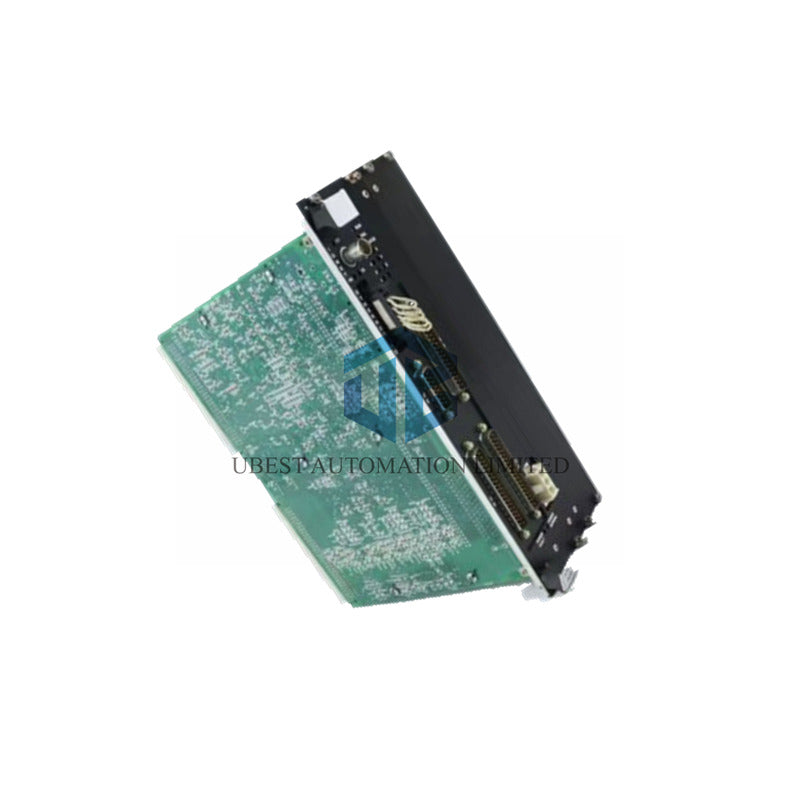
GE IS215VPROH2BD Mark VI - Turbine Protection Board
Manufacturer:
GE
Product No.:
IS215VPROH2BD
Condition:
In Stock
Product Type:
Turbine Protection Board
Product Origin:
USA
Weight:
500g
Shipping port:
Xiamen
Warranty:
12 months
UBEST – Trusted Global Automation Parts Supplier
We offer a wide range of in-stock industrial automation spare parts. All products come with a 12-month warranty and a 30-day refund for quality issues.
GE IS215VPROH2BD Turbine Protection Board - Emergency Safety Control
General Electric's IS215VPROH2BD delivers critical emergency overspeed protection for Mark VI turbine systems. This protection board ensures fail-safe operation with triple redundant design.
Technical Specifications
- Brand: General Electric
- Model: IS215VPROH2BD
- Product Type: Turbine Protection Board
- Series: Mark VI Speedtronic
- Operating Voltage: 24 V DC or 48 V DC
- Power Supply: 125 V DC input range
- Voltage Range: 70 V DC to 145 V DC
- Output Voltages: 5 V DC and 28 V DC
- MPU Frequency: 2 Hz to 20 kHz range
- Speed Accuracy: 0.05% of reading
Protection System Capabilities
- Emergency overspeed trip protection
- Three redundant VPRO board configuration
- Twelve relay control on TREG board
- Nine voting input relays
- Three trip solenoid groups
- Secondary TREG board drive capability
- Fail-safe operation design
- Redundant power paths
Input & Output Configuration
- Passive speed pickup inputs
- Generator voltage measurement
- Bus voltage monitoring
- Thermocouple input support
- 4-20 mA current signal inputs
- Voltage signal inputs available
- Trip interlock inputs
- Emergency stop functionality
Performance Characteristics
- Frame Rate: Up to 100 Hz maximum
- Processing Speed: 10/20/40 ms cycles
- MPU Output Resistance: 500 ohms
- MPU Inductance: 100 mH typical
- Short Circuit Current: 50 mA maximum
- Normal Mode Load: 10 kΩ input
- Cable Distance: 300 meters maximum
- Signal Integrity: Shielded pair required
Installation Procedure
- Power down VME I/O rack completely
- Insert board into designated slot
- Push top and bottom levers securely
- Tighten captive front panel screws
- Connect J3, J4, J5, J6 connectors
- Attach J7 for 125 V DC power
- Power up system gradually
- Check diagnostic LED indicators
System Indicators & Controls
- Eleven LED status indicators
- Run LED: Green operation light
- Status LED: Yellow condition indicator
- Fail LED: Red fault indication
- Front panel reset button
- Latching type connectors
- Secure cable connections
- Real-time status monitoring
Communication & Integration
- Ethernet IONet communication
- Control module interface
- TPRO terminal board connection
- TREG terminal board interface
- TRPG board coordination
- System network integration
- Data exchange capability
- Remote monitoring support
Package Contents
- One IS215VPROH2BD protection board
- Installation hardware kit
- Connection accessories
- Technical documentation
- Protective packaging materials
Shipping Services
- FedEx express delivery option
- UPS worldwide shipping
- DHL international service
- Package tracking included
- Secure packaging standard
- Fast order processing
Warranty Coverage
- 12-month product warranty
- Technical support services
- Installation assistance
- Replacement service
- Quality guarantee
Professional FAQ
- How many trip solenoids can this board control?
- The protection board manages up to three trip solenoids through TREG and TRPG terminal boards with redundant power paths.
- What redundancy modes does the system support?
- It operates in both simplex and Triple Modular Redundancy modes with voting inputs for maximum safety reliability.
- What communication interfaces are available?
- The board features Ethernet IONet communication for control module integration and real-time data exchange.
- How does the emergency overspeed protection work?
- Triple redundant VPRO boards in a dedicated module independently monitor speed and activate trip solenoids when needed.
- What is the maximum sensor cable distance?
- Sensors can be located up to 300 meters away using shielded pair cables with specified capacitance and resistance values.
© 2025 Ubest Automation Limited. All rights reserved.
Original Source: https://www.ubestplc.com/
Contact: sales@ubestplc.com Phone: +86 180 3000 5825